Chip design
From a one-paragraph brief to a GDS layout: Micius runs the whole chip design flow
Talk to an engineer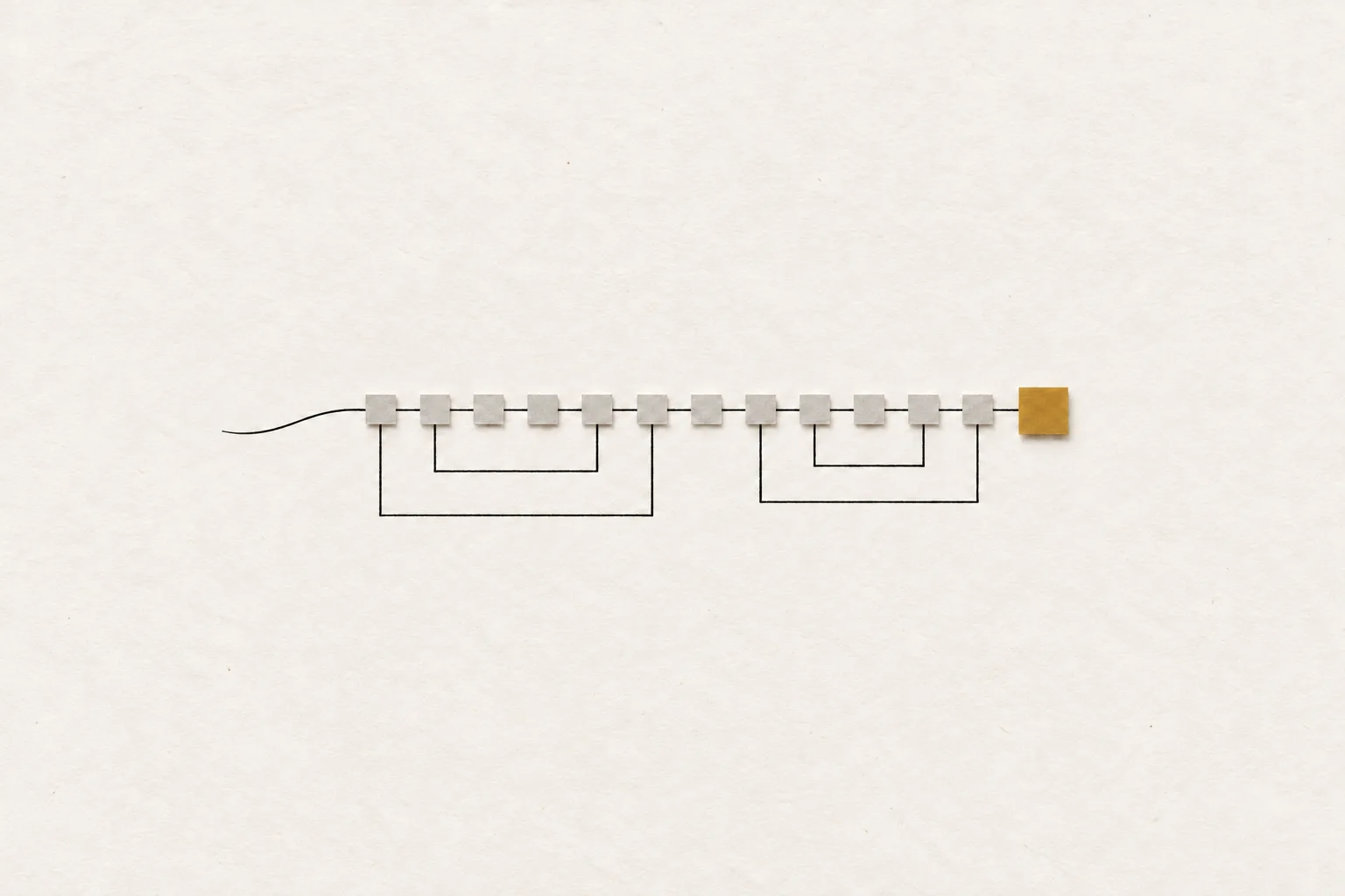
- 15 rounds
- of error, diagnosis, backtrack and rerun in one run
- +5.39 ns
- post-route worst setup slack at 100 MHz in one run; the 10 ns clock constraint was never relaxed
- 346 tool calls
- from brief to GDS in one session, with no human input
Getting a digital chip from a brief to a layout takes a dozen or more stages, and a failure at any of them can send you back several steps. Micius, Zhiman’s model, was given a one-paragraph brief and took it all the way to a GDS layout file, running the EDA tools itself and going back to fix each failure where it started.
Challenge
A dozen stages between a brief and a layout
Taking a digital chip from a brief to a layout means breaking down the requirements, settling the architecture, writing and simulating the RTL, then synthesis, floorplan, power network, clock tree, routing, timing analysis, gate-level simulation and finally the GDS layout file. Each stage has its own tools and scripts, and its report feeds the next.
The hard part is between stages. Many problems surface downstream but start upstream: a routing failure can trace back to synthesis, a timing miss to the architecture. Once the fix is in, everything after it has to run again. So the work passes back and forth between front-end and back-end engineers, and every handover means explaining the context again. For a block this size, that has typically meant a small team working together for a few days. Models in chip design have mostly handled one piece, such as writing RTL. Running the whole chain asks more: knowing where to go back to when something fails.
A chip design team gave the whole chain to Micius, Zhiman’s model. From one brief, it worked through to a GDS layout in a single session: 346 tool calls, 15 rounds of diagnosis, fixes and reruns, and no human input along the way.
Approach
From a paragraph to checkable constraints
The brief describes a real-time image filter chip for teaching: 3×3 Sobel edge detection on 8-bit greyscale images, thresholded to black or white against a configurable value. It sets hard constraints. Image size and threshold can change frame by frame; the sliding window must come from two line buffers, never a stored frame; no pixel may be lost, repeated or reordered. The target is 100 MHz at one pixel per clock cycle, on an open-source 45 nm teaching library, inside a 250×250 µm die, with source, testbench, constraints, scripts, netlist, GDS and a results report as deliverables.
Micius first broke the paragraph into constraints it could check one by one, then set up the project and wrote the RTL. Next it wrote a reference model from the spec alone, without looking at the RTL. A model derived from the RTL can share its mistakes, which makes them harder to spot; written separately, the two can disagree, so a match means something.
Lint came back clean. RTL simulation ran seven frames, from ordinary sizes down to a 4×4 frame, with thresholds at the extremes of 0 and 255. Micius rebuilt the output into images and compared them with the reference model pixel by pixel: all 51,289 matched.
Backtracking
Fixing problems where they start
Most of the errors came in the back end. Micius handled each the same way: read the error, find the cause, decide which stage it belonged to, fix it there and run forward again.
Round 11 shows how. Detailed routing failed because a constant net couldn’t be routed. The cause lay back in synthesis: the constant signals weren’t connected to tie cells, the cells that hold a fixed logic level. Micius went back to synthesis, added the tie cells, and reran floorplan, power network, clock tree and routing. Two other rounds went all the way back to the RTL: in round 7 it rewrote an absolute-value operation so the netlist was easier for the back-end tools to handle, and in round 5 it added a time-unit declaration the simulator needed. Every change and its reason is in the run log.
Illustrative flowA failure downstream, a fix upstream, and every stage in between run again.
Timing
Closing timing without slowing the clock
The first routed version missed timing badly. Setup slack, the margin a signal has before the next clock edge, was −7.18 ns at worst, with a total of −6,099 ns across failing paths. At 100 MHz each cycle lasts 10 ns, and the whole Sobel calculation sat in one cycle of logic.
Slowing the clock would have been easier. The decision Micius recorded was to keep the constraint and change the structure: it went back to the RTL, split the calculation into a two-stage pipeline and ran forward again. Worst slack came back to −1.82 ns. Design and timing repair in the back end closed the rest, ending at +5.39 ns worst setup slack, zero total negative slack, and +0.043 ns worst hold slack.
Illustrative flowThe constraint line stays put; two changes take worst slack from negative to positive.
Results
A layout and the evidence behind it
The exported GDS measures 250×250 µm as specified, and the router reports zero DRC violations. Synthesis produced 8,523 standard cells, and the layout holds 10,597 instances in all. Estimated total power is 3.97 mW. Both the RTL and the gate-level netlist were compared with the reference model, and all 51,289 pixels matched both times, so synthesis hadn’t broken the tested function.
Every deliverable the brief asked for is in the project, and every figure in the report comes from a tool’s own output, so an engineer can trace it back through the run log to the call that produced it.
The limits matter. This is a small teaching design on a teaching library; area and power were recorded but not optimised; timing was checked only at the typical corner; nothing was signed off. Micius hands back a design and a body of evidence to review, still well short of tape-out. Which conclusions hold and which checks to add is for the engineers to decide.
The same approach also works for
-
Back end for existing RTL
Take verified RTL and its constraints from synthesis to layout, going back to the stage at fault whenever one fails.
-
Timing closure
With the clock held, find the failing paths, weigh a structural change against back-end repair, and record each attempt for engineers to choose from.
-
Rerunning on another library
Move a design to a different cell library, rerun synthesis through layout, and compare area, timing and power.
-
Regression after a change
Rerun from the stage a change touches, then check the RTL and gate-level netlist against the reference model again.
How many handoffs does RTL to GDS take in your team?
Tell us how big a typical block is, which process and tool flow you use, and what sign-off requires. We’ll walk through a block with you and show what Micius takes on first.
Related use cases


Role training and onboarding
Turns scattered training documents into a knowledge map that people review, and answers new hires’ questions with the source attached.
TCAD modelling and simulation
Sets up, runs and explains device simulations.
PCB design
Describe a board in a paragraph; Micius picks parts, draws the schematic, routes the board and runs the checks, for an engineer to review.

EDA simulation
Writes RTL and testbenches, runs the EDA tools and fixes what fails, for an engineer to review.